PHYSICS S.S ONE(CURRENT ELECTRICITY)
SECOND TERM
WEEK: 5
CURRENT ELECTRICITY
We speak of
static electricity when the charge is at rest, but when the charge is in
motion, it is referred to as current electricity. Electrical energy is used for lighting,
Heating and operating electronic devices such as T.V, computers, high speed
trains etc. This energy is carried through conductors like wires.
Electric current, I, is defined as the rate of flow of electric
charge along a conductor. SI
unit is the ampere (A).
Current (I) =
From the definition above, Current, I = Charge ,Q Time ,t. Q = It
Example
Calculate the amount of current flowing through a bulb if 360
coulombs of charge flows through it in 3.5 minutes.
Solution
I = Q/t =
360/3.5x60= 1.714 A
Types of Electric Current
a) Direct current(d.c) – which flows in one direction only
b) Alternating current(a.c) – which reverses direction with a
given frequency
SIMPLE
ELECTRIC CIRCUIT
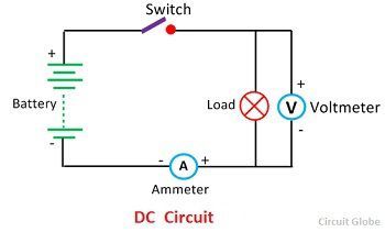
An electric is the path provided for the flow
of electric current. The circuit consists of the sources of electric energy
(e.g battery) connected through a conductor ( e.g a wire) to a load (e.g
electric bulb) and a key or switch. The switch serves to complete (close) or
break (open) the circuit. The ammeter to measure the current flow, a voltmeter
to measure the potential difference, a resistor or load and a rheostat to
adjust the flow of current.

Notes
a) A circuit that allows charges to move in a complete path when
the switch is closed is said to be a closed circuit.
b) A circuit that does not allow charges to move in a complete
path such a circuit is said to be an open (broken circuit). Open circuit can
also be as a result of loose connection of wires.
c) For clarity and neatness, symbols are used in representing an
electrical circuit.

Direction Of Flow of Electric
Conventionally, the flow of current is from the positive terminal
to the negative terminal of the cell. it is opposite to the direction of flow
of electrons.
The instrument for measuring electric current is called an ammeter
while electric current flow is controlled by a variable resistor.
COMPONENTS OF ELECTRIC CIRCUIT AND
THEIR SYMBOLS.

TYPES OF ELECTRIC CIRCUIT
There are 3 types of electric circuits.
1.
Closed circuit 2. Open circuit 3.
Short circuit
CLOSE CIRCUIT: is the circuit in which there is no gap (key close)
along the conducting path. In such a circuit the current flows through an
external resistor ( or load) and the bulb light up.
OPEN CIRCUIT: is the circuit with a gap or opening (key open) in
the conducting path. In such a circuit, the battery maintains no current in an
external resistor (or load) and the bulb does not light up.
SHORT CIRCUIT: is a closed circuit which has no load on it.
POTENTIAL DIFFERENCE (p.d)
The potential difference between any two points in an electric
field is defined as the workdone in moving a positive charge of 1 coulomb from
one point in the electric field to another.
ELECTROMOTIVE FORCE (e.m.f)
The e.m.f of a cell is defined as the p.d between the terminals of
a cell when it is not delivering any current in an external circuit (or when it
is in an open circuit). The units of e.m.f is the volt.
E.m.f can also be define as the total work done in driving one
coulomb of electricity around a circuit or the total energy per coulomb
obtained from a cell or battery.
E.m.f (E) =
RESISTANCE
Resistance can be defined as the opposition to the flow of charges
(electrons) or current. Its unit is ohm.
FACTORS AFFECTING ELECTRICAL RESISTANCE
Four factors affect the resistance of a conductor. These are: I.
Length of conductor (RαL)
II. Area of conductor ( Rα1/A) III. Temperature (RαT) IV. Types or substance of materials.
Resistance of a wire
(R) =
Example
1.
Find the resistance of a wire of
length 0.65x10⁻³mm, radius 2x10⁻⁴m and resistivity 3x10⁻⁶Ωm.
Solution
ρ = 3x10⁻⁶Ωm; l =
0.65x10⁻³mm; r = 2x10⁻⁴m, R= ?
(R) =
PARALLEL AND SERIES CONNECTION OF RESISTORS IN AN ELECTRIC CIRCUIT
Series Connection
When the resistors are connected end to ends. They are said to be
in series.
When they are connected, the equivalent resistance of the
combination is given by R = R1 + R2 + R3
Parallel Combination
When the resistors are arranged side by side such that their
corresponding ends join together at two common junctions X and Y as shown below,
the arrangement is known as parallel connection of the resistors.
The combined or equivalent resistance (R ) is given by
OHM’S LAW
Ohm’s law states that the current flowing through a metallic
conductor (e.g wire) is directly proportional to the potential difference
across this ends, provided that temperature and other physical conditions of
the conductors are kept constant.
V= IR
Ohm’s law is not obeyed by such conductors as radio valve e.g
diodes, transistors, rectifiers and gases.
Example
2.
Two resistors 5Ω each can be
combined to give an equivalent resistance of
Solution
Series combination: R = R1
+ R2 = 5 +5 =10 Ω
Parallel combination:
PRESENTATION
Step I: The teacher explains current electricity
StepII: The teacher explains electric circuit
Step III: The students mention the basic components of electric
circuit
Step IV: The teacher lists the components of electric circuit with
their respective symbol
Step V: The teacher states ohm’s law
Step VI: The teacher students are allow to ask questions
EVALUATION
The teacher evaluates the students by asking the following
questions:
I.
Differentiate between static electricity and current electricity.
II.
What is a short circuit
III.
State ohm’s law
IV.
What is the equivalent resistance of two resistors 4Ω and 7Ω
connected in parallel.

Comments
Post a Comment